Rabu, 17 Juni 2009

Jaringan Komputer

Jaringan komputer adalah sebuah sistem yang terdiri atas komputer dan perangkat jaringan lainnya yang bekerja bersama-sama untuk mencapai suatu tujuan yang sama. Tujuan dari jaringan komputer adalah:

* Membagi sumber daya: contohnya berbagi pemakaian printer, CPU, memori, harddisk
* Komunikasi: contohnya surat elektronik, instant messaging, chatting
* Akses informasi: contohnya web browsing

Agar dapat mencapai tujuan yang sama, setiap bagian dari jaringan komputer meminta dan memberikan layanan (service). Pihak yang meminta layanan disebut klien (client) dan yang memberikan layanan disebut pelayan (server). Arsitektur ini disebut dengan sistem client-server, dan digunakan pada hampir seluruh aplikasi jaringan komputer.

Klasifikasi Berdasarkan skala :

* Personal Area Network (PAN)
* Campus Area Network (CAN)
* Local Area Network (LAN)
* Metropolitant Area Network (MAN)
* Wide Area Network (WAN)
* Global Area Network (GAN)

Berdasarkan fungsi : Pada dasarnya setiap jaringan komputer ada yang berfungsi sebagai client dan juga server. Tetapi ada jaringan yang memiliki komputer yang khusus didedikasikan sebagai server sedangkan yang lain sebagai client. Ada juga yang tidak memiliki komputer yang khusus berfungsi sebagai server saja. Karena itu berdasarkan fungsinya maka ada dua jenis jaringan komputer:

* Client-server

Yaitu jaringan komputer dengan komputer yang didedikasikan khusus sebagai server. Sebuah service/layanan bisa diberikan oleh sebuah komputer atau lebih. Contohnya adalah sebuah domain seperti www.detik.com yang dilayani oleh banyak komputer web server. Atau bisa juga banyak service/layanan yang diberikan oleh satu komputer. Contohnya adalah server jtk.polban.ac.id yang merupakan satu komputer dengan multi service yaitu mail server, web server, file server, database server dan lainnya.

* Peer-to-peer

Yaitu jaringan komputer dimana setiap host dapat menjadi server dan juga menjadi client secara bersamaan. Contohnya dalam file sharing antar komputer di Jaringan Windows Network Neighbourhood ada 5 komputer (kita beri nama A,B,C,D dan E) yang memberi hak akses terhadap file yang dimilikinya. Pada satu saat A mengakses file share dari B bernama data_nilai.xls dan juga memberi akses file soal_uas.doc kepada C. Saat A mengakses file dari B maka A berfungsi sebagai client dan saat A memberi akses file kepada C maka A berfungsi sebagai server. Kedua fungsi itu dilakukan oleh A secara bersamaan maka jaringan seperti ini dinamakan peer to peer.

Topologi jaringan

Topologi jaringan adalah, hal yang menjelaskan hubungan geometris antara unsur-unsur dasar penyusun jaringan, yaitu node, link, dan station. Topologi jaringan dapat dibagi menjadi 5 kategori utama seperti di bawah ini.

* Topologi bintang
* Topologi cincin
* Topologi bus
* Topologi mesh
* Topologi pohon

Setiap jenis topologi di atas masing-masing memiliki kelebihan dan kekurangan. Pemilihan topologi jaringan didasarkan pada skala jaringan, biaya, tujuan, dan pengguna.


----------------
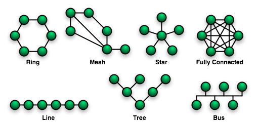
Topologi bintang
----------------

Topologi bintang merupakan bentuk topologi jaringan yang berupa konvergensi dari node tengah ke setiap node atau pengguna. Topologi jaringan bintang termasuk topologi jaringan dengan biaya menengah.

a. Kelebihan

* Kerusakan pada satu saluran hanya akan mempengaruhi jaringan pada saluran tersebut dan station yang terpaut.
* Tingkat keamanan termasuk tinggi.
* Tahan terhadap lalu lintas jaringan yang sibuk.
* Penambahan dan pengurangan station dapat dilakukan dengan mudah.

b. Kekurangan

* Jika node tengah mengalami kerusakan, maka seluruh jaringan akan terhenti.

c. Penanganan

* Perlunya disiapkan node tengah cadangan.

---------------
Topologi cincin
---------------

Topologi cincin adalah topologi jaringan berbentuk rangkaian titik yang masing-masing terhubung ke dua titik lainnya, sedemikian sehingga membentuk jalur melingkar membentuk cincin. Pada topologi cincin, komunikasi data dapat terganggu jika satu titik mengalami gangguan. Jaringan FDDI mengantisipasi kelemahan ini dengan mengirim data searah jarum jam
dan berlawanan dengan arah jarum jam secara bersamaan.

------------
Topologi bus
------------

Pada topologi Bus, kedua unjung jaringan harus diakhiri dengan sebuah terminator. Barel connector dapat digunakan untuk memperluasnya. Jaringan hanya terdiri dari satu saluran kabel yang menggunakan kabel BNC. Komputer yang ingin terhubung ke jaringan dapat mengkaitkan dirinya dengan mentap Ethernetnya sepanjang kabel. Linear Bus: Layout ini termasuk layout yang umum. Satu kabel utama menghubungkan tiap simpul, ke saluran tunggal komputer yang mengaksesnya ujung dengan ujung. Masing-masing simpul dihubungkan ke dua simpul lainnya, kecuali mesin di salah satu ujung kabel, yang masing-masing hanya terhubung ke satu simpul lainnya. Topologi ini seringkali dijumpai pada sistem client/server, dimana salah satu mesin pada jaringan tersebut difungsikan sebagai File Server, yang berarti bahwa mesin tersebut dikhususkan hanya untuk pendistribusian data dan biasanya tidak digunakan untuk pemrosesan informasi. Instalasi jaringan Bus sangat sederhana, murah dan maksimal terdiri atas 5-7 komputer. Kesulitan yang sering dihadapi adalah kemungkinan terjadinya tabrakan data karena mekanisme jaringan relatif sederhana dan jika salah satu node putus maka akan mengganggu kinerja dan trafik seluruh jaringan.

a. Keunggulan topologi Bus adalah pengembangan jaringan atau penambahan workstation baru dapat dilakukan dengan mudah tanpa mengganggu workstation lain.

b. Kelemahan dari topologi ini adalah bila terdapat gangguan di sepanjang kabel pusat maka keseluruhan jaringan akan mengalami gangguan.


--------------------------------
Topologi jala atau Topologi mesh
--------------------------------

Topologi jala atau mesh adalah sejenis topologi jaringan yang menerapkan hubungan antarsentral secara penuh. Jumlah saluran harus disediakan untuk membentuk jaringan ini adalah jumlah sentral dikurangi 1 (n-1, n = jumlah sentral). Tingkat kerumitan jaringan sebanding dengan meningkatnya jumlah sentral yang terpasang. Topologi ini selain kurang ekonomis juga relatif mahal dalam pengoperasiannya.


---------------------------------
Topologi pohon atau Topologi tree
---------------------------------

Topologi Jaringan Pohon (Tree) Topologi jaringan ini disebut juga sebagai topologi jaringan bertingkat. Topologi ini biasanya digunakan untuk interkoneksi antar sentral denganhirarki yang berbeda. Untuk hirarki yang lebih rendah digambarkan pada lokasi yang rendah dan semakin keatas mempunyai hirarki semakin tinggi. Topologi jaringan jenis ini cocok digunakan pada sistem jaringan komputer .

Pada jaringan pohon, terdapat beberapa tingkatan simpul (node). Pusat atau simpul yang lebih tinggi tingkatannya, dapat mengatur simpul lain yang lebih rendah tingkatannya. Data yang dikirim perlu melalui simpul pusat terlebih dahulu. Misalnya untuk bergerak dari komputer dengan node-3 kekomputer node-7 seperti halnya pada gambar, data yang ada harus melewati node-3, 5 dan node-6 sebelum berakhir pada node-7. Keungguluan jaringan model pohon seperti ini adalah, dapat terbentuknya suatu kelompok yang dibutuhkan pada setiap saat. Sebagai contoh, perusahaan dapat membentuk kelompok yang terdiri atas terminal pembukuan, serta pada kelompok lain dibentuk untuk terminal penjualan. Adapun kelemahannya adalah, apabila simpul yang lebih tinggi kemudian tidak berfungsi, maka kelompok lainnya yang berada dibawahnya akhirnya juga menjadi tidak efektif. Cara kerja jaringan pohon ini relatif menjadi lambat.


---------------
Topologi linier
---------------

Jaringan komputer dengan topologi linier biasa disebut dengan topologi linier bus, layout ini termasuk layout umum. Satu kabel utama menghubungkan tiap titik koneksi (komputer) yang dihubungkan dengan konektor yang disebut dengan T Connector dan pada ujungnya harus diakhiri dengan sebuah terminator. Konektor yang digunakan bertipe BNC (British Naval Connector), sebenarnya BNC adalah nama konektor bukan nama kabelnya, kabel yang digunakan adalah RG 58 (Kabel Coaxial Thinnet). Installasi dari topologi linier bus ini sangat sederhana dan murah tetapi maksimal terdiri dari 5-7 Komputer.

Tipe konektornya terdiri dari

1. BNC Kabel konektor ---> Untuk menghubungkan kabel ke T konektor.
2. BNC T konektor ---> Untuk menghubungkan kabel ke komputer.
3. BNC Barrel konektor ---> Untuk menyambung 2 kabel BNC.
4. BNC Terminator ---> Untuk menandai akhir dari topologi bus.

Keuntungan dan kerugian dari jaringan komputer dengan topologi linier bus adalah :

* Keuntungan, hemat kabel, layout kabel sederhana, mudah dikembangkan, tidak butuh kendali pusat, dan penambahan maupun pengurangan terminal dapat dilakukan tanpa mengganggu operasi yang berjalan.
* Kerugian, deteksi dan isolasi kesalahan sangat kecil, kepadatan lalu lintas tinggi, keamanan data kurang terjamin, kecepatan akan menurun bila jumlah pemakai bertambah, dan diperlukan Repeater untuk jarak jauh.

Topologi linear bus merupakan topologi yang banyak dipergunakan pada masa penggunaan kabel Coaxial menjamur. Dengan menggunakan T-Connector (dengan terminator 50ohm pada ujung network), maka komputer atau perangkat jaringan lainnya bisa dengan mudah dihubungkan satu sama lain. Kesulitan utama dari penggunaan kabel coaxial adalah sulit untuk mengukur apakah kabel coaxial yang dipergunakan benar-benar matching atau tidak. Karena kalau tidak sungguh-sungguh diukur secara benar akan merusak NIC (network interface card) yang dipergunakan dan kinerja jaringan menjadi terhambat, tidak mencapai kemampuan maksimalnya. Topologi ini juga sering digunakan pada jaringan dengan basis fiber optic (yang kemudian digabungkan dengan topologi star untuk menghubungkan dengan client atau node.).


---------
10BASE5
---------

10Base5 adalah sebuah standar implementasi pertama jaringan Ethernet. Standar ini sering juga disebut sebagai ThickNet karena memang jaringan ini menggunakan sebuah kabel koaksial (coaxial) tebal untuk menghubungkan komputer-komputer dalam membangun sebuah jaringan. Nama lainnya adalah Standard Ethernet, karena memang jenis ini merupakan implementasi jaringan Ethernet pertama kali.

10Base5 mendukung bandwidth maksimum hingga 10 Mbit/detik, meski dalam jaringan bandwidth yang dapat dicapainya hanya berkisar 4 Mbit/detik hingga 6 Mbit/detik karena banyaknya kolisi dalam jaringan yang mengurangi kecepatannya. 10Base5 dibuat berdasarkan spesifikasi IEEE 802.3 yang dibuat oleh Project 802.

Jaringan 10Base5 dihubungkan dengan menggunakan topologi bus, karena ia menggunakan sebuah kabel koaksial tebal yang panjang. Panjang maksimum sebuah segmen jaringan 10Base5 adalah 500 meter. Jika jarak jaringan melebihi 500 meter, maka dua segmen tersebut harus disatukan dengan menggunakan repeater.

Sebuah segmen jaringan 10Base5 sebaiknya tidak memiliki 100 komputer yang tergabung ke dalamnya. Berbeda dengan 10Base2 yang menghubungkan komputer secara langsung dengan kabel, pada jaringan 10Base5 terdapat sebuah transceiver yang dihubungkan ke kabel ThickNet, dengan menggunakan konektor yang dapat melubangi kabel yang disebut sebagai vampire tap.

Jaringan 10Base5 sering digunakan sebagai backbone dalam sebuah jaringan yang besar. Dalam konfigurasi yang biasa, transceiver dalam backbone ThickNet dapat dihubungkan dengan repeater, yang kemudian dapat menggabungkan segmen-segmen ThinNet yang lebih kecil ke backbone ThickNet. Dengan cara seperti ini, sebuah kombinasi antara standar 10Base5 dan 10Base2 dapat mendukung jumlah komputer yang cukup besar.

Nama 10Base5 dibuat dari komponen-komponen berikut:

* Kecepatan maksimum jaringan (10 Mbit/detik).
* Metode transmisi jaringan (baseband)
* Panjang segmen maksimal (500 meter, dengan pembuangan angka 0)

Jaringan 10Base5 merupakan teknologi jaringan yang kuno dan tidak diimplentasikan lagi pada jaringan komputer saat ini, meski beberapa perusahaan mungkin mempertahankannya. Kompleksitas dan keterbatasan bandwidth yang hanya mencapai 10 Mbit/detik menyebabkan jaringan ini "pensiun". Penggantinya adalah 10BaseT yang lebih sederhana, Fast Ethernet untuk kecepatan yang lebih tinggi, Gigabit Ethernet atau Fiber Distributed Data Interface (FDDI) jika hendak membuat backbone.


-----------------
Jaringan 10BASE/2
-----------------

10Base2 adalah sebuah jenis standar yang digunakan untuk mengimplementasikan jaringan berbasis teknologi Ethernet. 10Base2 juga disebut sebagai Thinnet atau Thin Coax karena teknologi jaringan ini menggunakan kabel koaksial (coaxial) tipis untuk menghubungkan komputer-komputer untuk membangun sebuah jaringan.

Secara teoritis, standar ini mendukung bandwidth hingga 10 Mbit/detik, tapi dalam implementasinya, hanya berkisar antara 4 Mbit/detik hingga 6 Mbit/detik, dikarenakan banyaknya kolisi yang terjadi di dalam jaringan. Jaringan 10Base2 dibangun berdasrkan spesifikasi IEEE 802.3 yang dkembangkan oleh Project 802.

Komputer-komputer dalam jaringan 10Base2 dihubungkan dengan menggunakan topologi bus, sehingga setiap komputer akan dihubungkan secara langsung dengan satu buah kabel panjang. Panjang maksimum segmen jaringan 10Base2 adalah 185 meter. Jika memang jarak lebih besar daripada 185 meter, maka dua segmen tersebut harus dihubungkan dengan menggunakan repeater. Sebuah segmen jaringan 10Base2 disarankan agar tidak menggunakan lebih dari 30 komputer, sebab jarak minimum antara komputer haruslah 50 cm (½ meter).

Setiap komputer dihubungkan dengan kabel dengan menggunakan konektor BNC. Pada ujung kabel, haruslah menggunakan BNC terminator yang diberi impedansi sebesar 50 ohm. Karena, jika tidak diberi terminator sinyal akan membalik dan mengakibatkan komunikasi jaringan menjadi tidak mungkin terjadi.

Nama 10Base2 datang dari komponen-komponen berikut:

* Kecepatan maksimum jaringan (10 Mbit/detik)
* Metode transmisi sinyal jaringan (Baseband)
* Panjang maksimum sebuah segmen (185 meter, tapi dibulatkan menjadi 200, dengan angka 0 dibuang).

Jaringan 10Base2 saat ini tidak diimplementasikan lagi karena memiliki dua permasalahan, yakni:

1. Karena kecepatan maksimum yang dimiliki jaringan 10Base2 adalah terbatas pada 10 Mbit/detik, jaringan akan terasa sangat lambat, khususnya pada jaringan yang banyak menggunakan bandwidth.
2. Jaringan 10Base2 menggunakan sebuah kabel linear panjang yang digunakan untuk menghubungkan komputer-komputer. Satu saja ada koneksi yang mengalami kerusakan (atau longgar), dapat menyebabkan keseluruhan jaringan menjadi terputus, dan untuk menelusuri kerusakanya, setiap segmen kabel dan koneksi ke setiap komputer harus dicek.

Karena dua masalah di atas, 10Base2 telah ditinggalkan dan penggunaan teknologi jaringan berpindah ke standar 10BaseT (untuk kecepatan lambat), Fast Ethernet, atau Gigabit Ethernet untuk kecepatan yang lebih tinggi.


--------
10BaseT
--------

10BaseT adalah sebuah standar yang digunakan untuk mengimplementasikan jaringan berbasis teknologi Ethernet. Dibandingkan dengan standar 10Base2 atau 10Base5, standar 10BaseT ini lebih populer, meski kecepatan yang ditawarkan adalah sama, yaitu 10 Megabit per detik. 10BaseT menggunakan kabel Unshielded Twisted-Pair (UTP) untuk menghubungkan komputer, dan menggunakan hub untuk membentuk sebuah jaringan.

10BaseT mendukung kecepatan hingga 10 Megabit per detik, tapi dalam kenyataannya kecepatan yang dapat diraihnya hanyalah berkisar antara 4 Megabit per detik hingga 6 Megabit per detik, karena adanya beberapa halangan seperti kolisi (tumbukan) paket data dalam jaringan. Standar ini dibangun berdasarkan spesifikasi IEEE 802.3 yang dikembangkan oleh Project 802.

Jaringan 10BaseT dihubungkan dengan menggunakan topologi star ke sebuah hub yang berada di tengah-tengah jaringan. Kabel UTP yang digunakan adalah kabel UTP Kategori 3, UTP Kategori 4, atau UTP Kategori 5, yang diberi ujung konektor RJ-45.

Panjang maksimum satu buah segmen jaringan 10BaseT adalah 100 meter. Jika jarak antara dua segmen melebihi jarak ini, maka dua segmen tersebut harus dihubungkan dengan menggunakan repeater. Jarak minimum sebuah segmen adalah 2.5 meter. Dengan menggunakan stackable hub (hub yang dapat ditumpuk), sebuah jaringan yang cukup besar dapat dibentuk dengan menggunakan standar ini. Meskipun standar ini mendukung hingga 1024 node, sebaiknya dalam satu jaringan jangan terdapat lebih dari 300 node agar kinerja yang lebih baik, mengingat semakin banyak node yang terhubung akan memperbanyak kolisi yang terjadi.

Nama 10BaseT diambil dari beberapa komponen yang menyusunnya, yakni:

* Kecepatan maksimum jaringan (10 Mbit/detik)
* Metode transmisi jaringan (Baseband)
* Kabel yang digunakan (Twisted-Pair).

Standar jaringan ini sudah dianggap usang, dan digantikan dengan standar 100BaseT (Fast Ethernet) atau bahkan Gigabit Ethernet (1000BaseT).

-------
10BaseF
-------

10BaseF adalah sebuah standar yang digunakan untuk mengimplementasikan jaringan dengan teknologi Ethernet. 10BaseF berbeda dari jenis-jenis Ethernet (10BaseT, 10Base2, 10Base5), karena standar ini menggunakan kabel serat optik, dan tidak menggunakan kabel tembaga seperti Unshielded twisted pair (UTP) atau kabel koaksial. 10BaseF dibuat berdasarkan spesifikasi IEEE 802.3 oleh Project 802.

Cara 10BaseF bekerja mirip dengan cara kerja 10BaseT, yakni dengan menggunakan topologi star dan menggunakan sebuah hub dengan interkoneksi serat optik untuk membentuk sebuah jaringan. Panjang maksimum sebuah kabel serat optik dalam standar 10BaseF adalah 2 kilometer. Kabel serat optik yang direkomendasikan adalah kabel yang memiliki diameter 62,5 mikron. Kabel ini dapat diakhiri dengan menggunakan konektor ST atau konektor SMA, tergantung hub yang digunakan. Standar ini menggunakan sebuah kabel dengan dua serat: satu serat digunakan untuk menerima data, dan satu serat lagi digunakan untuk mengirimkan data.

Standar 10BaseF

Standar 10BaseF terdiri dari tiga sub-standar yang dibedakan menurut jenis medianya:

* 10BaseFB, mendefinisikan transmisi data secara sinkron melalui kabel serat optik. Standar ini tidak banyak diimplementasikan karena mahal. Dengan menggunakan segmen 10BaseFB, beberapa buah hub serat optik dapat disambungkan satu sama lain, sedemikian rupa sama seperti pada 10BaseT, sehingga bisa lebih panjang. Setiap segmen dapat menampung 1024 komputer.
* 10BaseFL, mendefinisikan karakteristik jalur serat optik antara node dan hub/konsentrator. Standar ini menggantungkan standar yang lama, segmen Fiber-Optic Inter-Repeater Link (FOIRL), yang dikembangkan pada tahun 1980-an. 10BaseFL merupakan standar yang paling banyak diimplementasikan.
* 10BaseFP (Fiber Passive), mendefinisikan implementasi sebuah topologi star yang tidak menggunakan repeater. Segmen 10BaseFP hanya dapat mencapai panjang maksimum 500 meter dengan jumlah maksimum 33 komputer yang terkoneksi. Standar ini juga tidak banyak diimplementasikan.

Spesifikasi 10BaseF mempunyai beberapa karakteristik, sebagai berikut:

* Kecepatan maksimum jaringan: (10 Mbit/detik)
* Metode transmisi jaringan: satu frekuensi atau (Baseband)
* Jenis kabel yang digunakan: (serat optik).

Kabel serat optik ini umumnya digunakan untuk menghubungkan jaringan antara dua buah gedung berbeda.


--------
Ethernet
--------

Ethernet merupakan jenis skenario perkabelan dan pemrosesan sinyal untuk data jaringan komputer yang dikembangkan oleh Robert Metcalfe dan David Boggs di Xerox Palo Alto Research Center (PARC) pada tahun 1972.

Versi awal Xerox Ethernet dikeluarkan pada tahun 1975 dan di desain untuk menyambungkan 100 komputer pada kecepatan 2,94 megabit per detik melalui kabel sepanjang satu kilometer.

Disain tersebut menjadi sedemikian sukses di masa itu sehingga Xerox, Intel dan Digital Equipment Corporation (DEC) mengeluarkan standar Ethernet 10Mbps yang banyak digunakan pada jaringan komputer saat ini. Selain itu, terdepat standar Ethernet dengan kecepatan 100Mbps yang dikenal sebagai Fast Ethernet.

Asal Ethernet bermula dari sebuah pengembangan WAN di University of Hawaii pada akhir tahun 1960 yang dikenal dengan naman "ALOHA". Universitas tersebut memiliki daerah geografis kampus yang luas dan berkeinginan untuk menghubungkan komputer-komputer yang tersebar di kampus tersebut menjadi sebuah jaringan komputer kampus.

Proses standardisasi teknologi Ethernet akhirnya disetujui pada tahun 1985 oleh Institute of Electrical and Electronics Engineers (IEEE), dengan sebuah standar yang dikenal dengan Project 802. Standar IEEE selanjutnya diadopsi oleh International Organization for Standardization (ISO), sehingga menjadikannya sebuah standar internasional dan mendunia yang ditujukan untuk membentuk jaringan komputer. Karena kesederhanaan dan keandalannya, Ethernet pun dapat bertahan hingga saat ini, dan bahkan menjadi arsitektur jaringan yang paling banyak digunakan.

Jenis-jenis Ethernet

Jika dilihat dari kecepatannya, Ethernet terbagi menjadi empat jenis, yakni sebagai berikut:

* 10 Mbit/detik, yang sering disebut sebagai Ethernet saja (standar yang digunakan: 10Base2, 10Base5, 10BaseT, 10BaseF)
* 100 Mbit/detik, yang sering disebut sebagai Fast Ethernet (standar yang digunakan: 100BaseFX, 100BaseT, 100BaseT4, 100BaseTX)
* 1000 Mbit/detik atau 1 Gbit/detik, yang sering disebut sebagai Gigabit Ethernet (standar yang digunakan: 1000BaseCX, 1000BaseLX, 1000BaseSX, 1000BaseT).
* 10000 Mbit/detik atau 10 Gbit/detik. Standar ini belum banyak diimplementasikan.

Kecepatan Standar Spesifikasi IEEE Nama
10 Mbit/detik 10Base2, 10Base5, 10BaseF, 10BaseT IEEE 802.3 Ethernet
100 Mbit/detik 100BaseFX, 100BaseT, 100BaseT4, 100BaseTX IEEE 802.3u Fast Ethernet
1000 Mbit/detik 1000BaseCX, 1000BaseLX, 1000BaseSX, 1000BaseT IEEE 802.3z Gigabit Ethernet
10000 Mbit/detik 11mm/.ll


* Cara kerja *

Spesifikasi Ethernet mendefinisikan fungsi-fungsi yang terjadi pada lapisan fisik dan lapisan data-link dalam model referensi jaringan tujuh lapis OSI, dan cara pembuatan paket data ke dalam frame sebelum ditransmisikan di atas kabel.

Ethernet merupakan sebuah teknologi jaringan yang menggunakan metode transmisi Baseband yang mengirim sinyalnya secara serial 1 bit pada satu waktu. Ethernet beroperasi dalam modus half-duplex, yang berarti setiap station dapat menerima atau mengirim data tapi tidak dapat melakukan keduanya secara sekaligus. Fast Ethernet serta Gigabit Ethernet dapat bekerja dalam modus full-duplex atau half-duplex.

Ethernet menggunakan metode kontrol akses media Carrier Sense Multiple Access with Collision Detection untuk menentukan station mana yang dapat mentransmisikan data pada waktu tertentu melalui media yang digunakan. Dalam jaringan yang menggunakan teknologi Ethernet, setiap komputer akan "mendengar" terlebih dahulu sebelum "berbicara", artinya mereka akan melihat kondisi jaringan apakah tidak ada komputer lain yang sedang mentransmisikan data. Jika tidak ada komputer yang sedang mentransmisikan data, maka setiap komputer yang mau mengirimkan data dapat mencoba untuk mengambil alih jaringan untuk mentransmisikan sinyal. Sehingga, dapat dikatakan bahwa jaringan yang menggunakan teknologi Ethernet adalah jaringan yang dibuat berdasrkan basis First-Come, First-Served, daripada melimpahkan kontrol sinyal kepada Master Station seperti dalam teknologi jaringan lainnya.

Jika dua station hendak mencoba untuk mentransmisikan data pada waktu yang sama, maka kemungkinan akan terjadi collision (kolisi/tabrakan), yang akan mengakibatkan dua station tersebut menghentikan transmisi data, sebelum akhirnya mencoba untuk mengirimkannya lagi pada interval waktu yang acak (yang diukur dengan satuan milidetik). Semakin banyak station dalam sebuah jaringan Ethernet, akan mengakibatkan jumlah kolisi yang semakin besar pula dan kinerja jaringan pun akan menjadi buruk. Kinerja Ethernet yang seharusnya 10 Mbit/detik, jika dalam jaringan terpasang 100 node, umumnya hanya menghasilkan kinerja yang berkisar antara 40% hingga 55% dari bandwidth yang diharapkan (10 Mbit/detik). Salah satu cara untuk menghadapi masalah ini adalah dengan menggunakan Switch Ethernet untuk melakukan segmentasi terhadap jaringan Ethernet ke dalam beberapa collision domain.

* Frame Ethernet *

Ethernet mentransmisikan data melalui kabel jaringan dalam bentuk paket-paket data yang disebut dengan Ethernet Frame. Sebuah Ethernet frame memiliki ukuran minimum 64 byte, dan maksimum 1518 byte dengan 18 byte di antaranya digunakan sebagai informasi mengenai alamat sumber, alamat tujuan, protokol jaringan yang digunakan, dan beberapa informasi lainnya yang disimpan dalam header serta trailer (footer). Dengan kata lain, maksimum jumlah data yang dapat ditransmisikan (payload) dalam satu buah frame adalah 1500 byte.

Ethernet menggunakan beberapa metode untuk melakukan enkapsulasi paket data menjadi Ethernet frame, yakni sebagai berikut:

* Ethernet II (yang digunakan untuk TCP/IP)
* Ethernet 802.3 (atau dikenal sebagai Raw 802.3 dalam sistem jaringan Novell, dan digunakan untuk berkomunikasi dengan Novell NetWare versi 3.11 atau yang sebelumnya)
* Ethernet 802.2 (juga dikenal sebagai Ethernet 802.3/802.2 without Subnetwork Access Protocol, dan digunakan untuk konektivitas dengan Novell NetWare 3.12 dan selanjutnya)
* Ethernet SNAP (juga dikenal sebagai Ethernet 802.3/802.2 with SNAP, dan dibuat sebagai kompatibilitas dengan sistem Macintosh yang menjalankan TCP/IP)

Sayangnya, setiap format frame Ethernet di atas tidak saling cocok/kompatibel satu dengan lainnya, sehingga menyulitkan instalasi jaringan yang bersifat heterogen. Untuk mengatasinya, lakukan konfigurasi terhadap protokol yang digunakan via sistem operasi.

* Topologinya *

Ethernet dapat menggunakan topologi jaringan fisik apa saja (bisa berupa topologi bus, topologi ring, topologi star atau topologi mesh) serta jenis kabel yang digunakan (bisa berupa kabel koaksial (bisa berupa Thicknet atau Thinnet), kabel tembaga (kabel UTP atau kabel STP), atau kabel serat optik). Meskipun demikian, topologi star lebih disukai. Secara logis, semua jaringan Ethernet menggunakan topologi bus, sehingga satu node akan menaruh sebuah sinyal di atas bus dan sinyal tersebut akan mengalir ke semua node lainnya yang terhubung ke bus.

-------------
Fast Ethernet
-------------

Fast Ethernet merupakan sebuah sebutan untuk teknologi jaringan Ethernet yang menawarkan kecepatan yang lebih tinggi dibandingkan dengan standar Ethernet biasa. Kecepatan yang ditawarkannya mencapai 100 megabit per detik. Standar-standar yang dibuat untuk teknologi ini adalah 100BaseTX, 100BaseFX, 100BaseT4, dan 100BaseVG. Disebut juga 100BaseX.

Spesifikasi yang diratifikasi sebagai IEEE 802.3u pada tahun 1995 ini menjadi evolusi yang mengizinkan transmisi data yang jauh lebih cepat (10 kali lipat) dibandingkan dengan standar Ethernet yang sebelumnya, dengan menggunakan metode media access control yang sama, yakni Carrier Sense Multiple Access with Collision Detection (CSMA/CD). Selain itu, format frame yang digunakannya pun juga sama dengan Ethernet biasa, sehingga kompatibel dengan Ethernet. Pengabelan yang digunakan pun juga sama, yakni menggunakan kabel twisted pair, atau kabel serat optik meski kabel koaksial (yang digunakan oleh Ethernet 10Base2 dan 10Base5) telah ditinggalkan.

Standar ini dapat bekerja dalam modus full-duplex atau half-duplex dan dapat diimplementasikan di dalam jaringan yang menggunakan hub atau switch

------
Duplex
------

Duplex adalah sebuah istilah dalam bidang telekomunikasi yang merujuk kepada komunikasi dua arah.
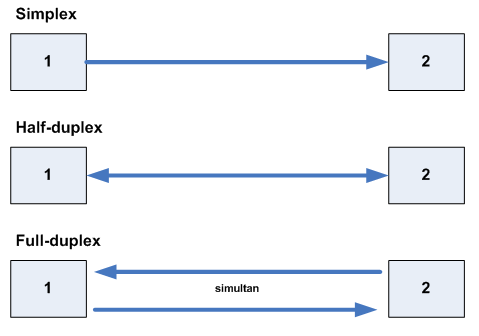
Cara kerja transmisi Simplex, full duplex, dan Half duplex

Terdapat dua metode duplexing, yakni

* Full-duplex
* Half-duplex

a. Full-duplex

Dalam komunikasi full-duplex, dua pihak yang saling berkomunikasi akan mengirimkan informasi dan menerima informasi dalam waktu yang sama, dan umumnya membutuhkan dua jalur komunikasi.

Komunikasi full-duplex juga dapat diraih dengan menggunakan teknik multiplexing, di mana sinyal yang berjalan dengan arah yang berbeda akan diletakkan pada slot waktu (time slot) yang berbeda. Kelemahan teknik ini adalah bahwa teknik ini memotong kecepatan transmisi yang mungkin menjadi setengahnya.

b. Half-duplex

Half-duplex merupakan sebuah mode komunikasi di mana data dapat ditransmisikan atau diterima secara dua arah tapi tidak dapat secara bersama-sama. Contoh paling sederhana adalah walkie-talkie, di mana dua penggunanya harus menekan sebuah tombol untuk berbicara dan melepaskan tombol tersebut untuk mendengar. Ketika dua orang menggunakan walkie-talkie untuk berkomunikasi pada satu waktu tertentu, hanya salah satu di antara mereka yang dapat berbicara sementara pihak lainnya mendengar. Jika kedua-duanya mencoba untuk berbicara secara serentak, kondisi "collision" (tabrakan) pun terjadi dan kedua pengguna walkie-talkie tersebut tidak dapat saling mendengarkan apa yang keduanya kirimkan.

--------
Simplex
--------

Simplex adalah salah satu bentuk komunikasi antara dua belah pihak, di mana sinyal-sinyal dikirim secara satu arah. Metode transmisi ini berbeda dengan metode full-duplex yang mampu mengirim sinyal dan menerima secara sekaligus dalam satu waktu, atau half-duplex yang mampu mengirim sinyal dan menerima sinyal meski tidak dalam satu waktu. Transmisi secara simplex terjadi di dalam beberapa teknologi komunikasi, seperti siaran televisi atau siaran radio.

Transmisi simplex tidak digunakan dalam komunikasi jaringan karena node-node dalam jaringan umumnya membutuhkan komunikasi secara dua arah. Memang, beberapa komunikasi dalam jaringan, seperti video streaming, terlihat seperti simplex, tapi sebenarnya lalu lintas komunikasi terjadi secara dua arah, apalagi jika protokol TCP yang digunakan sebagai protokol lapisan transportnya.
Berkas:Simplex-Duplex.png


-------------------------
Lebar pita atau Bandwidth
-------------------------

Bandwidth / Lebar pita (bahasa Inggris: bandwidth) dalam teknologi komunikasi adalah perbedaan antara frekuensi terendah dan frekuensi tertinggi dalam rentang tertentu. Sebagai contoh, line telepon memiliki bandwidth 3000Hz (Hertz), yang merupakan rentang antara frekuensi tertinggi (3300Hz) dan frekuensi terendah (300Hz) yang dapat dilewati oleh line telepon ini.

Pengertian Bandwidth

Bandwidth adalah luas atau lebar cakupan frekuensi yang digunakan oleh sinyal dalam medium transmisi. Dalam kerangka ini, Bandwidth dapat diartikan sebagai perbedaan antara komponen sinyal frekuensi tinggi dan sinyal frekuensi rendah. frekuensi sinyal diukur dalam satuan Hertz. sinyal suara tipikal mempunyai Bandwidth sekitar 3 kHz, analog TV broadcast (TV) mempunyai Bandwidth sekitar 6 MHz. Bandwidth diartikan juga sebagai takaran jarak frekuensi. Dalam bahasa mudahnya, adalah sebuah takaran lalu lintas data yang masuk dan yang keluar. Dalam dunia hosting, kita di berikan jatah Bandwidth setiap bulan tergantung seberapa dalam kita merogoh kocek. Habisnya Bandwidth ditentukan seberapa banyak kita mengupload atau mendownload. Makin banyak anda melakukan aktivitas upload, ditambah makin banyaknya pengunjung yang mengakses, maka makin berkurang jatah Bandwidth yang diberikan. Misalkan, www.namasitus.com diberi jatah Bandwidth sebesar 1,5 Giga dalam sebulan. Dan sudah sejak bulan Desember rasanya jatah Bandwidth yang diberikan kurang. Pada bulan Desember, jatah Bandwidth habis sehari sebelum tahun baru. Dan berturut-turut bulan Januari, Februari, Maret dan April habis dalam 3 minggu. Otomatis, dalam seminggu terakhir didats.net tidak bisa diakses.

Digital Bandwidth

Digital Bandwidth Digital Bandwidth adalah jumlah atau volume data yang dapat dikirimkan melalui sebuah saluran komunikasi dalam satuan bits per second tanpa distorsi. Analog Bandwith

Analog Bandwidth

Sedangkan analog Bandwidth adalah perbedaan antara frekuensi terendah dengan frekuensi tertinggi dalam sebuah rentang frekuensi yang diukur dalam satuan Hertz (Hz) atau siklus per detik, yang menentukan berapa banyak informasi yang bisa ditransimisikan dalam satu saat.

Bandwidth Komputer

Bandwidth Komputer Di dalam jaringan Komputer, Bandwidth sering digunakan sebagai suatu sinonim untuk data transfer rate yaitu jumlah data yang dapat dibawa dari sebuah titik ke titik lain dalam jangka waktu tertentu (pada umumnya dalam detik). Jenis Bandwidth ini biasanya diukur dalam bps (bits per second). Adakalanya juga dinyatakan dalam Bps (bytes per second). Suatu modem yang bekerja pada 57,600 bps mempunyai Bandwidth dua kali lebih besar dari modem yang bekerja pada 28,800 bps. Secara umum, koneksi dengan Bandwidth yang besar/tinggi memungkinkan pengiriman informasi yang besar seperti pengiriman gambar/images dalam video presentation.

Alokasi Bandwidth

Alokasi Bandwidth Alokasi atau reservasi Bandwidth adalah sebuah proses menentukan jatah Bandwidth kepada pemakai dan aplikasi dalam sebuah jaringan. Termasuk didalamnya menentukan prioritas terhadap berbagai jenis aliran data berdasarkan seberapa penting atau krusial dan delay-sensitive aliran data tersebut. Hal ini memungkinkan penggunaan Bandwidth yang tersedia secara efisien, dan apabila sewaktu-waktu jaringan menjadi lambat, aliran data yang memiliki prioritas yang lebih rendah dapat dihentikan, sehingga aplikasi yang penting dapat tetap berjalan dengan lancar. Besarnya saluran atau Bandwidth akan berdampak pada kecepatan transmisi. Data dalam jumlah besar akan menempuh saluran yang memiliki Bandwidth kecil lebih lama dibandingkan melewati saluran yang memiliki Bandwidth yang besar. Kecepatan transmisi tersebut sangat dibutuhkan untuk aplikasi Komputer yang memerlukan jaringan terutama aplikasi real-time, seperti videoconferencing. Penggunaan Bandwidth untuk LAN bergantung pada tipe alat atau medium yang digunakan, umumnya semakin tinggi Bandwidth yang ditawarkan oleh sebuah alat atau medium, semakin tinggi pula nilai jualnya. Sedangkan penggunaan Bandwidth untuk WAN bergantung dari kapasitas yang ditawarkan dari pihak ISP, perusahaan harus membeli Bandwidth dari ISP, dan semakin tinggi Bandwidth yang diinginkan, semakin tinggi pula harganya. sebuah teknologi jaringan baru dikembangkan dan infrastruktur jaringan yang ada diperbaharui, aplikasi yang akan digunakan umumnya juga akan mengalami peningkatan dalam hal konsumsi Bandwidth. Video streaming dan Voice over IP ([[VoIP]]) adalah beberapa contoh penggunaan teknologi baru yang turut mengkonsumsi Bandwidth dalam jumlah besar.

Tips Menghemat Bandwidth Internet

Tips Menghemat Bandwidth Internet Tips ini sangat berguna jika anda memasang internet yang menggunakan paket quota Bandwidth / Volume Based. 1. Menonaktifkan fungsi untuk load images dan sound. Jika anda melakukan browsing ke suatu situs dan hanya membutuhkan info text nya saja di situs tersebut anda bisa menonaktifkan fungsi untuk load images dan sound. Untuk Firefox : Tools -> Options -> Content Untuk IE : Tools -> Internet Options -> Advanced 2. Mematikan setting update automatic. Mematikan setting update automatic pada windows, antivirus maupun software yang lain dan pindah ke setting ke manual update. Karena ada beberapa program yang kita install melakukan download update secara automatis. 3. Install Add-ons Adblock Plus. Plugin ini berfungsi untuk mengeblok iklan-iklan yang muncul di suatu situs kalo kita membuka situs tersebut. Untuk firefox anda bisa menginstall add-ons Adblock plus (https://addons.mozilla.org/en-US/firefox/addon/1865). add-ons firefox ini mampu mengeblok iklan gambar dan iklan flash. 4. Menggunakan program kompresi images seperti toolnel. Dengan program ini, maka data akan dikompres terlebih dahulu sebelum masuk ke Komputer kita. Anda bisa mendownload di http://www.toonel.net/downloads.html 5. Menggunakan Web mail yang support AJAX Gunakan layanan email yang support AJAX dimana tampilan bekerja efisien sehingga data yang kita download lebih kecil. Web mail yang support AJAX antara lain GMail dan Yahoo Mail dengan versi barunya. 6. Gunakan salah satu browser saja. Gunakan salah satu browser saja, misalnya kalau Firefox gunakanlah Firefox terus, kl Internet Explorer gunakanlah Internet Explorer terus, jangan berpindah-pindah, karena setiap browser memiliki cache sendiri, sehingga jika Anda membuka situs yang sudah pernah anda kunjungi, maka browser tersebut tidak akan mendownload seluruh data lagi, karena beberapa sudah tersimpan di browser Komputer anda berupa cache.


Kamis, 28 Mei 2009

How to Configure Load Balancing in a Cisco Router

When would you need this: When you are using a dynamic routing protocol, and have more than one path to destination networks.

The first fact to be set is that ALL router platforms support load balancing. And in a short description, load balancing is the operation in which the router forwards packets in different routes to the same destination. This happens when there is more than one entry in the routing table for the same destination network.

There are two types of load balancing:

1. Multiple entries to the same destination with equal metrics.

In this situation, protocols like RIP, RIPv2, IGRP, EIGRP, and OSPF automatically does the operation and no configuration is needed.

2. Multiple entries to the same destination with different metrics.

With a complex metric calculation, like IGRP and EIGRP, it is rare to get metrics to be equal to the same destination for different paths. In this case, configuration is needed.

You can configure something called ‘variance’. The variance value, determines the percentage that you are willing tolerate in choosing a secondary path. If the value of the variance is chosen to be 1, this means that only the paths with equal best metric will be used. And a value of 1.2, for example, means that the best path as well as the paths with a metric up to 1.2 of best path’s metric will be used.

A numerical example is,

For a variance of 1.3

If the best path’s metric is 1000, paths of metric in the range of 1000 to 1300 will be used. And remember that we are talking about multiple paths to the same destination.

And one more important note, we are talking about paths derived from the same routing protocol, i.e, paths with the same administrative distance.

The configuration of unequal path load balancing for IGRP and EIGRP is done with a single command:

Router(config-router)#variance X

Where X represent the value of the variance that you want to use.

Per-Packet and Per-Destination Load Balancing

There are two types of load balancing; Per-Packet and Per-Destination. In the Per-Packet load balancing, packets going to the same destination are sent over different paths. This way, you will guarantee that all paths to the destination network are being used. But using this method causes great amount of load on the routers’ resources and low-end routers may crash. Also, the packets may arrive out of order because of different network latencies in different paths.

Using the Per-Destination load balancing, packets going to one destination pass through one path. This way, you will lower the load on the router. But the different paths will not be utilized to the best.

To activate Per-Destination load balancing, issue the following command on the interface that you want to use this method of load balancing,

Router(config-if)#ip route-cache

And to activate Per-Packet load balancing use,

Router(config-if)#no ip route-cache

Newer switching schemes such as Cisco Express Forwarding (CEF) allow you to do per-packet and per-destination load-balancing more quickly. However, this method requires some extra resources to deal with maintaining CEF entries and adjacencies.

How to Copy IOS From One Cisco Router to Another

When would you need this: When you want to copy IOS file from one router to another for the purposes of upgrade or install. This is usually required when you do not have a TFTP server around.

Special Requirements: The flash size of the destination router should be adequate for the new IOS file size.

On the source router that contains the IOS file that you want to copy, issue the following command:

Router(config)#tftp-server flash:/SOURCE-IOS-FILE.bin

Where SOURCE-IOS-FILE.bin is the name of the IOS file that you want to copy. If you are using a router that has PCMCIA flash car, replace the ‘flash:’ with ‘slot0:’ or ‘slot1:’ in the previous command, depending on the slot that contains the file that you want to copy.

This command will make the router act as a TFTP server. And the rest of the procedure is done on the target router and can be found on this link.

After you complete the copy operation, issue the command:

Router(config)#no tftp-server flash:/SOURCE-IOS-FILE.bin


Rabu, 27 Mei 2009

How to Configure PPP on a Cisco Router

When would you need this: When you are creating a WAN link. And also when the other end of a WAN link is NOT a Cisco router. Point-to-Point Protocol can be used in synchronous, asynchoronous, HSSI, and ISDN links.

1. Get to the interface configuration mode and issue the following command,

Router(config-if)#encapsulation ppp

2. If you want to configure authentication (which is almost always the case), go through the following steps:

a. Choose the authentication type; Password Authentication Protocol (PAP), or Challenge Handshake Authentication Protocol (CHAP).

Router(config-if)#ppp authentication XXX

where XXX is the authentication type which can be: pap, chap, pap chap, or chap pap. The last two choices are to use the other authentication type when the first one fails.

CHAP is strongly recommended over PAP for two reasons. First, PAP sends the username and password in plaintext, while CHAP sends hashed challenges only. Second is that CHAP does an operation similar to periodic re-authentication in the middle of the communication session such that it provides more security than PAP.

b. Set a username and a password that the remote router would use to connect to your local router. You can define many username-password pairs for many PPP connections to the same router.

Router(config)#username USER password PASS

where USER is the host name of the remote router, and PASS is its password. Issue this command once for each PPP connection. For example if you are connecting RouterA to RouterB and RouterC, on RouterA issue this command once for each remote router.

c. Now you can set the username and password that you local router would use to access the remote router. For PAP authentication, you can specify the username and password that the local router will send to the remote router for authentication using the following command,

Router(config-if)#ppp pap sent-username USER passwrod PASS

For CHAP, two commands are used,

Router(config-if)#ppp chap hostname USER

Router(config-if)#ppp chap password PASS

The usernames and passwords are case sensitive, so be careful when writing them. This way, you will have to write the hostname and secret password of the remote router in your local router and write the hostname and secret password of your local router into your remote using the 'username' command.

If you do not set the username and password that will be sent from the local router to the remote router for authentication, the router will use its hostname and secret password instead.

3. You can monitor the quality of the serial link that is using PPP with the following command,

Router(config-if)#ppp quality PERCENT

where PERCENT is the minimum accepted link quality. If the link quality drops below PERCENT, the link will be shutdown and considered bad.

4. If the available bandwidth is small, you might consider compressing the data being transmitted using the following command,

Router(config-if)#ppp compress YYY

where YYY is the compression type which can be predictor or stacker.

Note: The compression might affect the system performance because it increases the CPU load. Check the CPU load with ‘show process cpu’ and disable the compression if the CPU load is over 65%.

5. To troubleshoot PPP, you can use the following commands,

Router#debug ppp negotioations

Router#debug ppp packets

Router#debug ppp errors

Router#debug ppp authentication


How to Configure Inter-VLAN Routing on a Cisco Router

When would you need this: When you want to perform routing between different VLANs.

Special Requirements: You have to make sure that your router support the frame tagging technology used between the switches.

Before jumping into the router configuration, you have to configure a port in the switch that will be connected to the router to be a trunk port. And keep remembering the VLAN tagging method that you configured the switch to use (ISL or 802.1Q, 802.10, or LANE).

What will be done in this procedure is creating logical interfaces inside the single physical interface that will be linking the switch to the router. These logical interfaces will be treated as separate interfaces in the routing decisions.

1. Remove the IP address from the physical interface, and turn it on,

Router(config-if)#no ip address

Router(config-if)#no shutdown

2. Create a logical interface to be assigned to one of the VLANs

Router(config-if)#int fastethernet 0/0.X

You can change the ‘fastethernet’ to the type you have and the ‘0/0’ with the interface number that you are using.

X represent the logical interface number (not number of logical interfaces). You can use any number here, but I think it is better to use the same number of the VLAN that you will assign to this logical interface. For example, for the logical interface that you will use for VLAN 5 use ‘int fastethernet 0/0.5'. This way, you will easily know which interface refers to which VLAN.

3. Assign the logical interface to a VLAN number

Router(config-subif)#encapsulation XXX Y

where XXX is the encapsulation type you are using for the VLANs (ex: isl or dot1q which is 802.1Q)

and Y is the VLAN number that this logical interface will be assigned to.

4. Assign an IP address to the logical interface

Router(config-subif)#ip address XXX.XXX.XXX.XXX YYY.YYY.YYY.YYY

where XXX.XXX.XXX.XXX and YYY.YYY.YYY.YYY are the IP address and the subnet mask,respectively, you want to use. Remember to give the logical interface an IP address that is lying in the range of the available IP addresses in the VLAN you assigned it to. This interface will be the gateway to the hosts connected to this VLAN. This means that you should do the addressing of the logical interface, you do it exactly the way you do the physical interfaces usually.

Repeat the steps 2 to 4 for each VLAN that you want.

5. Configure static or dynamic routing in the way you need it. And treat the logical interfaces the exact same way you treat the physical interfaces when doing the routing.

If you like some VLANs (ie, networks) not to participate in the routing, you can either not include them in the routing protocol or not assign a logical interface for them.

6. Configure access-lists in the way you find appropriate to filter the traffic going from one VLAN to another and apply them to the logical interfaces the same way you apply them to physical interfaces.

Implementation notes:

1. If you plan to let routing updates go through the router from one VLAN to another, it is necessary to turn off split-horizon. Split-horizon technology forbids the update coming from one interface to go out the same interface. Slit-horizon can be turned off using the following command issued in the physical interface:

Router(config-if)#no ip split-horizon

2. Without the access-lists, there would not be much point of doing VLANs and inter-VLAN routing because without the VLANs everyone would be able to communicate with everyone else.

3. Most switches support trunks on FastEthernet or faster interfaces, and do not support the old Ethernet with 10Mbps.

How to Configure Site-to-Site VPN in Cisco Routers

When would you need this: When you want to create a secure tunnel to transfer data between two sites without the use of VPN concentrator or other security devices.

Special Requirements: The routers used must support IPSec. Most of Cisco routers do. Another need is that both sides use a static public IP address to connect to the Internet.

We will go through the steps to be done on one side and the same steps must be repeated on the other side too. The encryption of data will depend on a shared-key. This way, we will not need specialized CAs or RSA methodologies.

1. Create Internet Key Exchange (IKE) key policy. The policy used for our case is policy number 9, because this policy requires a pre-shared key.

Router(config)#crypto isakmp policy 9

Router(config-isakmp)#hash md5

Router(config-isakmp)#authentication pre-share

2. Setup the shared key that would be used in the VPN,

Router(config)#crypto isakmp key VPNKEY address XXX.XXX.XXX.XXX

where,

VPNKEY is the shared key that you will use for the VPN, and remember to set the same key on the other end.

XXX.XXX.XXX.XXX the static public IP address of the other end.

3. Now we set lifetime for the IPSec security associations,

Router(config)#crypto ipsec security-association lifetime seconds YYYYY

where YYYYY is the associations lifetime in seconds. It is usually used as 86400, which is one day.

4. Configure an extended access-list to define the traffic that is allowed to be directed through the VPN link,

Router(config)#access-list AAA permit ip SSS.SSS.SSS.SSS WIL.DCA.RDM.ASK DDD.DDD.DDD.DDD WIL.DCA.RDM.ASK

where,

AAA is the access-list number

SSS.SSS.SSS.SSS WIL.DCA.RDM.ASK is the source of the data allowed to use the VPN link.

DDD.DDD.DDD.DDD WIL.DCA.RDM.ASK is the destination of the data that need to pass though the VPN link.

5. Define the transformations set that will be used for this VPN connection,

Router(config)#crypto ipsec transform-set SETNAME BBBB CCCCC

where,

SETNAME is the name of the transformations set. You can choose any name you like.

BBBB and CCCCC is the transformation set. I recommend the use of “esp-3des esp-md5-hmac”. You can also use “esp-3des esp-sha-hmac”. Any one of these two will do the job.

6. After defining all the previous things, we need to create a cypto-map that associates the access-list to the other site and the transform set.

Router(config)#crypto map MAPNAME PRIORITY ipsec-isakmp

Router(config-crypto-map)#set peer XXX.XXX.XXX.XXX

Router(config-crypto-map)#set transform-set SETNAME

Router(config-crypto-map)#match address AAA

where,

MAPNAME is a name of your choice to the crypto-map

PRIORITY is the priority of this map over other maps to the same destination. If this is your only crypto-map give it any number, for example 10.

XXX.XXX.XXX.XXX the static public IP address of the other end

SETNAME is the name of the transformations set that we configured in step 5

AAA is the number of the access-list that we created to define the traffic in step 4

7. The last step is to bind the crypto-map to the interface that connects the router to the other end.

Router(config-if)#crypto map MAPNAME

where MAPNAME is the name of the crypto-map that we defined in step 6.

Now, repeat these steps on the other end, and remember to use the same key along with the same authentication and transform set.

Note: If you want to implement multiple VPN connections to multiple sites, you can do this by repeating the steps 2 to 7 (except step 3) for each VPN connection. The different crypto-maps and their assignments differentiate between the different VPN connections.

For troubleshooting purposes, you can use the following commands,

show crypto isakmp sa

show crypto ipsec sa

show crypto engine connections active

and show crypto map

Upgarde IOS CISCO Router

IOS Software Installation and Upgrade Procedure

This procedure applies to the following Cisco products:

  • Cisco 10001
  • Cisco 14001
  • Cisco 1600-R
  • Cisco 1700
  • Cisco 2600
  • Cisco 3600
  • Cisco 3700
  • Cisco 4000
  • Cisco 4500
  • Cisco 4700
  • Cisco AS53001
  • Cisco MC3810
1. Not currently supported in COMPASS.

Contents


Introduction

This document explains the procedure for upgrading a Cisco IOS® Software image on Access router platforms. The examples provided from the 2600 and 3600 Series Routers also apply to the list of router platforms mentioned below. The Cisco IOS software file names may vary depending on the Cisco IOS software version, feature set, and platform.The following Cisco series routers are addressed in this document:

  • Cisco 1000 Series Routers
  • Cisco 1400Series Routers
  • Cisco 1600-R Series Routers
  • Cisco 1700 Series Routers
  • Cisco 2600 Series Routers
  • Cisco 3600 Series Routers
  • Cisco 3700 Series Routers
  • Cisco 4000 Series Routers
  • Cisco 4700 Series Routers
  • Cisco AS5300 Series Routers
  • Cisco MC3810 Series Routers

The information in this document is based on Cisco IOS Software Release 12.0 or later.

The Field Engineer must receive permission from Cisco VISE that a software image upgrade is required, BEFORE carrying out any of these procedures.

Before You Begin

Step 1: Install a TFTP Server
A Trival File Transfer Protocol (TFTP) server or a Remote Copy Protocol (RCP) server application must be installed on a TCP/IP-ready workstation or PC. Once the application is installed, a minimal level of configuration must be performed.

  • Note: Cisco no longer supply or support their own TFTP Server application, however searching within your favourite search engine for "TFTP Server" will locate a third party TFTP application for you. Alternatively, you may find Cisco's unsupported TFTP Server application on the COMPASS CD.
  1. First, the TFTP application must be configured to operate as a TFTP server as opposed to a TFTP client.
  2. The outbound file directory must be specified. This is the directory in which the Cisco IOS Software images are stored. Most TFTP applications provide a set-up routine to assist in these configuration tasks.

Step 2: Request which IOS Software Image is to be used.
The Field Engineer must ask the VISE engineer or the customer, which image is to be upgraded. It is not the responsibility of the Field Engineer to recommend software image versions. The software image may be provided by the customer, and so the Field Engineer must ask the Cisco VISE engineer for directions.

Step 3: Download the Cisco IOS Software Image
Download the Cisco IOS Software image into your workstation or PC from the Cisco website (http://www.cisco.com).


Software Installation and Upgrade Procedures

Routers with Internal Flash (for example, 2600 Series Routers)
Routers with PCMCIA Flash cards (for example, 3600 Series Routers)


Cisco 2600 Series Routers Upgrade Procedure

Step 1: Establish a console session to the router

Even if it is possible to connect to the router through a telnet session, it is strongly recommended to be directly connected to the router using the console port. The reason is that if something goes wrong during the upgrade, it might be necessary to be physically located next to the router to power-cycle it. Moreover, the telnet connection will be lost while the router is rebooting during the upgrade procedure.

A rolled cable (usually a flat black cable) is used to connect the console port of the router to one of the COM ports of the PC.

Once the PC is connected to the console port of the router, you need to open Hyperterminal on the PC, and use the following settings:

     Speed 9600 bits per second

8 databits

0 parity bits

1 stop bit

No Flow Control

Note: If you are getting any garbage characters in the hyperterminal session, this means that you have not set the hyperterminal properties properly, or the config-register of the router is set to a non-standard value for which the console connection speed is higher than 9600 bps. Check the value of the config-register using the show version command (shown in the last line of the output) and ensure it is set to 0x2102 or 0x102. It is necessary to reload the router for a configuration register change to take effect. Once you are sure the console speed is set to 9600 bps on the router side, you should check the hyperterminal properties as above .

Booting Problems

Once you are connected to the console port of the router, you might notice that the router is either in ROMmon or Boot mode. These two modes are used for recovery and/or diagnostic procedures. If you do not see the usual router prompt, you should follow the recommendations below to proceed with the upgrade procedure installation.

  1. Router boots in rommon mode, and the following message appears when you issue dir flash: command.
  2. rommon 1 > dir flash:
    device does not contain a valid magic number
    dir: cannot open device "flash:"
    rommon 2 >

    When you see the above error message, it means the Flash is empty or the filesystem is corrupted. A Xmodem console download procedure using ROMmon may then be necessary.

  3. Router boots in boot mode, with the following messages on the console:
  4. router(boot)>
    device does not contain a valid magic number
    boot: cannot open "flash:"
    boot: cannot determine first file name on device "flash:"

When you get the above error messages on the console output, it means the Flash is empty or the file system is corrupted. Copy a valid image on the Flash by following the procedures provided in this document.

Step 2: Verify that the TFTP server has IP connectivity to the router

The TFTP server must have a network connection to the router, and must be able to ping the IP address of the router targeted for a TFTP software upgrade. To achieve this, the router interface and the TFTP server must have:

  • an IP address in the same range, or
  • a default gateway configured.

To verify this, check the IP address of the TFTP server.

Step 3: Copy the new image into the Flash memory of the 2600 Series Router through the TFTP server
  1. Now that you have IP connectivity and can ping between the computer acting as a TFTP server and the router, you can copy the Cisco IOS Software image into the Flash.

    Note: Before copying, make sure you have started the TFTP server software on your PC and that you have the filename mentioned in the TFTP server root directory. We recommend that you keep a backup of the router/access server configuration before upgrading. The upgrade itself does not affect the configuration (which is stored in nonvolatile RAM (NVRAM). However, this might happen if the right steps are not followed properly.

    For RCP applications, substitute RCP for every occurrence of TFTP. For example, use the copy rcp flash command instead of the copy tftp flash command.

    2600> enable
    Password:xxxxx
    2600#
    2600# copy tftp flash

    If necessary, you can copy an image from one device to another.

  2. Specify the IP address of the TFTP server.

    When prompted, enter the IP address of the TFTP server as in the following example:

    Address or name of remote host []? 10.10.10.2
  3. Specify the filename of the new Cisco IOS Software image.

    When prompted, enter the filename of the Cisco IOS Software image to be installed, as in the following example:

    Source filename []? c2600-i-mz.121-14.bin

    Note: The filename is case sensitive, so be sure to enter it correctly.

  4. Specify the destination filename.

    This is the name the new software image will have when it is loaded onto the router. The image can be named anything, but common practice is to enter the same image filename.

    Destination filename []? c2600-i-mz.121-14.bin

    Note: If you see the below error message:

    %Error copying tftp://10.10.10.2/c2600-i-mz.121-14.bin
    (Not enough space on device)

    This indicates that there is not enough room available in Flash to copy the image. You need to erase a file(s) before copying the new image from the TFTP server.

  5. Upgrade the new image from a TFTP server
    2610#copy tftp flash
    Address or name of remote host []? 10.10.10.2
    Source filename []? c2600-i-mz.121-14.bin
    Destination filename [c2600-i-mz.121-14.bin]?y
    Accessing tftp://10.10.10.2/c2600-i-mz.121-14.bin...
    Erase flash: before copying? [confirm]y !---If there is not enough
    !--- memory available, erase the Flash
    Erasing the flash filesystem will remove all files! Continue? [confirm]y
    Erasing device... eeeeeeeeeeeeeeeeeeeeeeeeeeeeeeeeeeeeeeeeeeeeeeeeeeeeee
    eeeeeeeeee ...erased
    Erase of flash: complete
    Loading c2600-i-mz.121-14.bin from 10.10.10.2 (via Ethernet0/0): !!!!!!!!
    !!!!!!!!!!!!!!!!!!!!!!!!!!!!!!!!!!!!!!!!!!!!!!!!!!!!!!!!!!!!!!!!!!!!!!!!!
    !!!!!!!!!!!!!!!!!!!!!!!!!!!!!!!!!!!!!!!!!!!!!!!!!!!!!!!!!!!!!!!!!!!!!!!!!
    !!!!!!!!!!!!!!!!!!!!!!!!!!!!!!!!!!!!!!!!!!!!!!!!!!!!!!!!!!!!!!!!!!!!!!!!!
    !!!!!!!!!!!!!!!!!!!!!!!!!!!!!!!!!!!!!!!!!!!!!!!!!!!!!!!!!!!!!!!!!!!!!!!!!
    !!!!!!!!!!!!!!!!!!!!!!!!!!!!!!!!!!!!!!!!!!!!!!!!!!!!!!!!!!!!!!!!!!!!!!!!!
    !!!!!!!!!!!!!!!!!!!!!!!!!!!!!!!!!!!!!!!!!!!!!!!!!!!!!!!!!!!!!!!!!!!!!!!!!
    !!!!!!!!!!!!!!!!!!!!!!!!!!!!!!!!!!!!!!!!!!!!!!!!!!!!!!!!!!!!!!!!!!!!!!!!!
    !!!!!!!!!!!!!!!!!!!!!!!!!!!!!!!!!!!!!!!!!!!!!!!!!!!!!!!!!!!!!!!!!!!!!!!!!
    !!!!!!!!!!!!!!!!!!!!!!!!!!!!!!!!!!!!!!!!!!!!!!!!!!!!!!!!!!!!!!!!!!!!!!!!!
    !!!!!!!!!!!!!!!!!!!!!!!!!!!!!!!!!!!!!!!!!!!!!!!!!!!!!!!!!!!!!!!!!!!!!!!!!
    !!!!!!!!!!!!!!!!!!!!!!!!!!!!!!!!!!!!!!!!!!!!!!!!!!!!!!!!!!!!!!!!!!!!!!!!!
    !!!!!!!!!!!!!!!!!!!!!!!!!!!!!!!!!!!!!!!!!!!!!!!!!!!!!!!!!!!!!!!!!!!!!
    [OK - 4501480/9001984 bytes]

    Verifying checksum... OK (0xAC8A)
    4501480 bytes copied in 56.88 secs (80383 bytes/sec)

    The copying process takes several minutes; the time differs from network to network. During the copy process, messages are displayed to indicate which file has been accessed.

    The exclamation point "!" indicates that the copy process is taking place. Each exclamation point indicates that ten packets have been transferred successfully. A checksum verification of the image occurs after the image is written to Flash memory.

After you have upgraded the Flash, you need to reload the router using the reload command.

Before you reload the router, you need to check two things:

  • The value of the config-register - You can check this using the show version command. The value is shown in the last line of the show version output. It should be set to 0x2102.
      2610#configure terminal
      Enter configuration commands, one per line. End with CNTL/Z.
      2610(config)#config-register 0x2102
      2610(config)#^Z
  • The other files on the Flash - If the first file in the Flash is not the Cisco IOS Software image, but a configuration file or something else, then you need to configure a boot system statement in order to boot the specified image. Otherwise, the router will try to boot with the configuration file or the first file in the Flash; this will not work. If there is only one file in the Flash which is the Cisco IOS Software image, then this step is not necessary.
      2610#configure terminal
      Enter configuration commands, one per line. End with CNTL/Z.
      2610(config)#no boot system
      2610(config)#boot system flash c2600-i-mz.121-14.bin
      2610(config)#^Z

Note: If you type the reload command, the router asks you if you want to save the configuration. You should be very cautious here. The reason is that if the router is in boot mode for instance, it is a subset of the full Cisco IOS software which is running and there is no routing functionality. Therefore, all the routing configuration is gone in the running configuration and if you save the configuration at this time, then you erase the good startup-configuration in NVRAM and replace it by the incomplete running-configuration. Save the configuration only if you are sure that you have the full configuration in the output of show run. It is NOT necessary to save the configuration to take into account the new config-register if this one has been changed previously. That is done automatically.

2610#reload

System configuration has been modified. Save? [yes/no]: y
Building configuration...
[OK]
Proceed with reload? [confirm]y

Verify that the router is running with the proper image. After the reload is complete, the router should be running the desired Cisco IOS Software image. Use the show version command to verify.

2610#show version
00:22:25: %SYS-5-CONFIG_I: Configured from console by console
Cisco Internetwork Operating System Software
IOS (tm) C2600 Software (C2600-I-M), Version 12.1(14), RELEASE SOFTWARE (fc1)
Copyright (c) 1986-2002 by cisco Systems, Inc.
Compiled Mon 25-Mar-02 20:33 by kellythw
Image text-base: 0x80008088, data-base: 0x80828788

ROM: System Bootstrap, Version 11.3(2)XA4, RELEASE SOFTWARE (fc1)

2610 uptime is 22 minutes
System returned to ROM by reload
System image file is "flash:c2600-i-mz.121-14.bin"


Cisco 3600 Series Routers (with PCMCIA cards) Upgrade Procedure

Step 1: Establish a console session to the router

See Establish a console session to the router for more information.

Note: Once connected to the router through the console port, if you get a ">" or "rommon >" prompt, your router is in ROM monitor (ROMmon) mode. If the router is showing the "router (boot)>" prompt, then the router is in boot mode. See booting problems for steps to handle either of these situations.

Step 2: Verify the amount of free space on the Flash memory card (PCMCIA slot)

At this point, you need to verify that you have enough space in the Flash memory card to copy the new image. If there is not enough memory, you need to delete some files to make enough space. In some situations, if the image is very large, you may need to delete the current image in the Flash memory card.

To determine the amount of free space, and to show files currently located in slot0: or slot1:, issue the dir{device:} command.

3600#dir slot1:
Directory of slot1:/

1 -rw- 2779832 c3640-i-mz.113-11c.bin
2 -rw- 3748760 c3640-i-mz.120-22.bin

Verify that the name and the file size are correct.

If you find that there is not enough space, you can delete the file. The delete{device:}[filename] command deletes the file.

3600#delete slot1:
Delete filename []? c3640-i-mz.113-11c.bin
Delete slot1:c3640-i-mz.113-11c.bin? [confirm]y

Note: Do not reload or powercycle the router if there is not a valid image in the Flash; this causes the router to boot into rommon or bootmode.

Step 3: Verify that the TFTP server has IP connectivity to the router

The TFTP server must have a network connection to the router and must be able to ping the IP address of the router targeted for a TFTP software upgrade. To achieve this, the router interface and the TFTP server must have:

  • an IP address in the same range, or
  • a default gateway configured

To verify this, check the IP address of the TFTP server.

Step 4: Copy the new image into the Flash memory card through the TFTP server

Now that you have IP connectivity and can ping between the computer acting as a TFTP server and the router, you can copy the image into the right slot.

Note: Before copying, make sure you have started the TFTP server software on your PC and that you have the filename mentioned in the TFTP server root directory. We recommend that you keep a backup of the router/access server configuration before upgrading. The upgrade itself does not affect the configuration (which is stored in nonvolatile RAM -NVRAM). However, this may happen if the right steps are not followed properly.

For RCP applications, substitute RCP for every occurrence of TFTP. For example, use the copy rcp {device:} command instead of the copy tftp {device:} command.

If necessary, you can copy an image from one device to another.

3600#copy tftp: slot1:
Address or name of remote host []? 171.68.173.10
Source filename []? c3640-i-mz.122-7b.bin
Destination filename [c3640-i-mz.122-7b.bin]?
Accessing tftp://171.68.173.10/c3640-i-mz.122-7b.bin...
Erase slot1: before copying? [confirm]n !--- Here you are specifying "n"
!--- because there is enough memory available.
Loading c3640-i-mz.122-7b.bin from 171.68.173.10 (via Ethernet1/0):
!!!!!!!!!!!!!!!!!!!!!!!!!!!!!!!!!!!!!!!!!!!!!!!!!!!!!!!!!!!!!!!!!!!!!!!!!
!!!!!!!!!!!!!!!!!!!!!!!!!!!!!!!!!!!!!!!!!!!!!!!!!!!!!!!!!!!!!!!!!!!!!!!!!
!!!!!!!!!!!!!!!!!!!!!!!!!!!!!!!!!!!!!!!!!!!!!!!!!!!!!!!!!!!!!!!!!!!!!!!!!
!!!!!!!!!!!!!!!!!!!!!!!!!!!!!!!!!!!!!!!!!!!!!!!!!!!!!!!!!!!!!!!!!!!!!!!!!
!!!!!!!!!!!!!!!!!!!!!!!!!!!!!!!!!!!!!!!!!!!!!!!!!!!!!!!!!!!!!!!!!!!!!!!!!
!!!!!!!!!!!!!!!!!!!!!!!!!!!!!!!!!!!!!!!!!!!!!!!!!!!!!!!!!!!!!!!!!!!!!!!!!
!!!!!!!!!!!!!!!!!!!!!!!!!!!!!!!!!!!!!!!!!!!!!!!!!!!!!!!!!!!!!!!!!!!!!!!!!
!!!!!!!!!
[OK - 5996844/11993088 bytes]

Verifying checksum... OK (0x13F0)
5996844 bytes copied in 67.708 secs (89505 bytes/sec)
3600#

Use the dir slot1: command to check whether the image has been copied to slot1. Below, you can see that the new image c3640-i-mz.122-7b.bin has been copied on the PCMCIA slot1:

3600#dir slot1:
Directory of slot1:/

2 -rw- 3748760 c3640-i-mz.120-22.bin
3 -rw- 5996844 c3640-i-mz.122-7b.bin
Step 5: Set boot statements to load the new image upon startup

After copying the image through TFTP, you may need to tell the router which image to load upon boot up.

Checking Current Boot Statements

At this point, the new image is now in the slot1. You need to set the router to boot the new image. By default, the router boots the first available image (the default is enabled when there are no boot statements in the configuration).

3600#show running-config
Building configuration...

Current configuration:
!
version 12.0
service timestamps debug uptime
service timestamps log uptime
no service password-encryption
!
hostname 3600
!
boot system flash slot1:c3640-i-mz.120-22.bin
!
ip subnet-zero
!

The commands appear at the begginning of the configuration. In our example above, it shows the router has a boot system command configured as boot system flash slot1:c3640-i-mz.120-22.bin.

If you have boot system command entries in your configuration, you need to remove them from the configuration. For more information on removing boot entries, refer to the next section.

Removing Previous Boot Statements

To remove the commands, enter into configuration terminal mode. From the configuration mode, you can negate any command by typing "no" in front of each boot statement. The following example illustrates the removal of an existing boot statement.

3600#configure terminal
Enter configuration commands, one per line. End with CNTL/Z.
3600(config)#no boot system flash slot1:c3640-i-mz.120-22.bin
3600(config)#^Z
3600#

The statement "no boot system flash slot1:c3640-i-mz.120-22.bin" is removed from the configuration. Verify that the command has been removed by issuing the show running-config command.

Setting New Boot Statements

Now set the router to boot the new image. Issue the following command to set the boot system parameter:

boot system flash slot#:{imagename} (imagename = name of the new Cisco IOS software image)

3600#configure terminal
Enter configuration commands, one per line. End with CNTL/Z.
3600(config)#boot system flash slot1:c3640-i-mz.122-7b.bin
3600(config)#^Z
3600#write memory
3d01h: %SYS-5-CONFIG_I: Configured from console by vty0
Building configuration...
3600#

Be sure to verify that you are using config-register 0x2102 by issuing the show version command. If it is set up differently, you can change it by issuing the following command in configuration mode:

3600#configure terminal
Enter configuration commands, one per line. End with CNTL/Z.
3600(config)#config-register 0x2102
3600(config)#^Z

After changing the config-register, the change takes place at the next reload.

Step 6: Reboot the router to load the new image

For the router to run the new Cisco IOS software image, you need to reload the router. Make sure you have saved the configuration by issuing the copy running-config starting-config or write memory commands.

3600#write memory
3d01h: %SYS-5-CONFIG_I: Configured from console by vty0 (127.0.0.11)
Building configuration...
3600#reload
Step 7: Verify the upgrade

After the router comes up, make sure you are currently running the new version of code, by issuing the show version command.

3640#show version
Cisco Internetwork Operating System Software
IOS (tm) 3600 Software (C3640-I-M), Version 12.2(7b), RELEASE SOFTWARE (fc1)
Copyright (c) 1986-2002 by cisco Systems, Inc.
Compiled Mon 04-Mar-02 20:23 by pwade
Image text-base: 0x600089A8, data-base: 0x60A6A000

ROM: System Bootstrap, Version 11.1(19)AA, EARLY DEPLOYMENT RELEASE SOFTWARE (f)

Router uptime is 2 minutes
System returned to ROM by reload
System image file is "slot1:c3640-i-mz.122-7b.bin"

cisco 3640 (R4700) processor (revision 0x00) with 59392K/6144K bytes of memory.

Processor board ID 10524422
R4700 CPU at 100Mhz, Implementation 33, Rev 1.0
Bridging software.
X.25 software, Version 3.0.0.
4 Ethernet/IEEE 802.3 interface(s)
DRAM configuration is 64 bits wide with parity disabled.
125K bytes of non-volatile configuration memory.
4096K bytes of processor board System flash (Read/Write)
20480K bytes of processor board PCMCIA Slot0 flash (Read/Write)
20480K bytes of processor board PCMCIA Slot1 flash (Read/Write)

Configuration register is 0x2102

Verify that the version 12.2(7b) is correct and the config-register is set to 0x2102.

Page last updated on: 05/18/2007 21:23:42
All contents are Copyright © 1992–2007 Cisco Systems, Inc. All rights reserved.

Truble Proses :

Note: In step 1 or after the upgrade, if the router boots into rommon mode or boot mode and you have one of the following case:

rommon 1 > dir flash:

device does not contain a valid magic number

dir: cannot open device "flash:"

rommon 2 >

or

router(boot)>

device does not contain a valid magic number

boot: cannot open "flash:"

boot: cannot determine first file name on device "flash:"

This means that the flash is empty or the file system is corrupted. In this case, you have to consider using the procedure of Upgrading or Installing the IOS from ROMmon mode.

Before starting the procedure of IOS upgrade or installation, you will need to install TFTP server software on a PC connected to the router Ethernet interface. There are many free downloadable TFTP servers’ software on the Internet, however, our recommendation is Free TFTP Server 6.0.

Afterwards, you make sure to direct the TFTP server to the folder containing the new IOS image that you have.

If you are using this procedure to upgrade the IOS file and you router works fine, it is preferred to backup the old IOS file before starting the upgrade procedure. For this purpose, refer to the IOS backup procedure .

1. Create a console connection with the default settings (9600 baud, 8 databits, 0 parity bits, 1 stop bit, no flow control).

2. If your flash or IOS file are corrupted and your router goes directly to router boot mode (Router(boot)#), go to step 4. If your router has some problems and boots into the ROMmon mode directly(rommon 1> or >), go to step 3. If your router boots normally, interrupt the router boot sequence by pressing Ctrl-Break once the router is powered on. This will take you to ROMmon mode with the prompt:

rommon 1>

Or

>

3. Change the value of the configuration register to 0x2101 to instruct the router to boot into router boot mode. Afterwards, reload the router.

If you have the ‘rommon 1>’ prompt use the commands:

rommon 1> confreg 0x2101

rommon 2> reset

While if you have the ‘>’ prompt, use:

> o/r 0x2101

> i

4. Now you are in the router boot mode with the prompt (Router(boot)#), you will need to give a valid IP address and default-gateway address to the router so it can communicate with the TFTP server.

Router(boot)>enable

Router(boot)#configure terminal

Router(boot)(config)#interface ethernet 0

Router(boot)(config-if)#ip address ZZZ.ZZZ.ZZZ.ZZZ 255.255.255.0

Router(boot)(config-if)#no shutdown

Router(boot) (config-if)#exit

Router(boot)(config)#ip default-gateway YYY.YYY.YYY.YYY

5. Check the connectivity between the router and the TFTP server with the ‘ping’ command.

6. Start the copying of the new IOS file from the TFTP server to the flash.

Router(boot)#copy tftp flash

Now you will be asked for the IP address of the TFTP server

Address or name of remote host [255.255.255.255]? XXX.XXX.XXX.XXX

Then, the source file name,

Source file name? cXXXX-X-X.XXX-XXX.bin

Please note that the file name is case sensitive and make sure that the TFTP server’s working directory is the one containing the new IOS file.

Afterwards, you will be asked for a destination file name,

Destination file name [cXXXX-X-X.XXX-XXX.bin]?

It is advised that you keep the file name unchanged for future reference.

Accessing file 'cXXXX-X-X.XXX-XXX.bin' on XXX.XXX.XXX.XXX...

Loading cXXXX-X-X.XXX-XXX.bin from XXX.XXX.XXX.XXX (via Ethernet0):

! [OK] Device needs erasure before copying new file

Erase flash device before writing? [confirm]y

Copy 'cXXXX-X-X.XXX-XXX.bin' from server as 'cXXXX-X-X.XXX-XXX.bin' into Flash

WITH erase? [yes/no]yes

Erasing device...

eeeeeeeeeeeeeeeeeeeeeeeeeeeeeeeeeeeeeeeeeeeee

eeeeeeeeeeeeeeeeeeeeeeeeeeeeeeeeeeeeeeeeeeeee

eeeeeeeeeeeeeeeeeeeeeeeeeeeeeeeeeeee ...erased

Loading cXXXX-X-X.XXX-XXX.bin from XXX.XXX.XXX.XXX (via Ethernet0): !!!!!!!!!!!!!!!!!!!!!!!!!!!!!!!!!!!!!!!!!!!!!!!

!!!!!!!!!!!!!!!!!!!!!!!!!!!!!!!!!!!!!!!!!!!!!!!!!!!!!!!!!!!

!!!!!!!!!!!!!!!!!!!!!!!!!!!!!!!!!!!!!!!!!!!!!!!!!!!!!!!!!!!

!!!!!!!!!!!!!!!!!!!!!!!!!!!!!!!!!!!!!!!!!!!!!!!!!!!!!!!!!!!

!!!!!!!!!!!!!!!!!!!!!!!!!!!!!!!!!!!!!!!!!!!!!!!!!!!!!!!!!!!

!!!!!!!!!!!!!!!!!!!!!!!!!!!!!!!!!!!!!!!!!!!!!!!!!!!!!!!!!!!

!!!!!!!!!!!!!!!!!!!!!!!!!!!!!!!!!!!!!!!!!!!!!!!!!!!!!!!!!!!

!!!!!!!!!!!!!!!!!!!!!!!!!!!!!!!!!!!!!!!!!!!!!!!!!!!!!!!!!!!

!!!!!!!!!!!!!!!!!!

[OK - xxxxxx/yyyyyyy bytes]Verifying checksum... OK (0x6526)

Flash device copy took 00:yy:yy [hh:mm:ss]

Router(boot)#

7. Change back the configuration register value to 0x2102.

Router(boot)#configure terminal

Router(boot)(config)#config-register 0x2102

Router(boot)(config)#exit

Router(boot)#

8. Reload the router

Router(boot)#reload

System configuration has been modified. Save? [yes/no]: no

Building configuration...

[OK]

Proceed with reload? [confirm]

9. Everything should look fine now, and you should be getting the regular (Router>) prompt. To check the version and file name of the new IOS, use the ‘show version’ command.


Rabu, 04 Maret 2009

Mengenal Asam Urat

Asam Urat sering dialami oleh banyak orang sekarang ini. Bahkan, orang yang masih tergolong muda juga sering ditimpa penyakit ini. Sebenarnya, seperti apa penyakit ini? Apa saja gejala, penyebab, dan solusinya? Serta makanan apa yang menjadi pantangan? Berikut kita akan membahasnya.

Yang dimaksud dengan asam urat adalah sisa metabolisme zat purin yang berasal dari makanan yang kita konsumsi. Ini juga merupakan hasil samping dari pemecahan sel dalam darah.
Purin sendiri adalah zat yang terdapat dalam setiap bahan makanan yang berasal dari tubuh makhluk hidup. Dengan kata lain, dalam tubuh makhluk hidup terdapat zat purin ini, lalu karena kita memakan makhluk hidup tersebut, maka zat purin tersebut berpindah ke dalam tubuh kita. Berbagai sayuran dan buah-buahan juga terdapat purin. Purin juga dihasilkan dari hasil perusakan sel-sel tubuh yang terjadi secara normal atau karena penyakit tertentu.
Normalnya, asam urat ini akan dikeluarkan dalam tubuh melalui feses (kotoran) dan urin, tetapi karena ginjal tidak mampu mengeluarkan asam urat yang ada menyebabkan kadarnya meningkat dalam tubuh. Hal lain yang dapat meningkatkan kadar asam urat adalah kita terlalu banyak mengkonsumsi bahan makanan yang mengandung banyak purin. Asam urat yang berlebih selanjutnya akan terkumpul pada persendian sehingga menyebabkan rasa nyeri atau bengkak.
Penderita asam urat setelah menjalani pengobatan yang tepat dapat diobati sehingga kadar asam urat dalam tubuhnya kembali normal. Tapi karena dalam tubuhnya ada potensi penumpukan asam urat, maka disarankan agar mengontrol makanan yang dikonsumsi sehingga dapat menghindari makanan yang banyak mengandung purin.

Kesimpulan singkat tentang asam urat :

*Gejala Asam Urat*
1. Kesemutan dan linu
2. Nyeri terutama malam hari atau pagi hari saat bangun tidur
3. Sendi yang terkena asam urat terlihat bengkak, kemerahan, panas dan nyeri luar biasa pada malam dan pagi.

*Solusi Mengatasi Asam Urat*
1. Melakukan pengobatan hingga kadar asam urat kembali normal. Kadar normalnya adalah 2.4 hingga 6 untuk wanita dan 3.0 hingga 7 untuk pria.
2. Kontrol makanan yang dikonsumsi.
3. Banyak minum air putih. Dengan banyak minum air putih, kita dapat membantu membuang purin yang ada dalam tubuh.

*Makanan yang Dihindari (mengandung banyak purin)*
1. Lauk pauk seperti jeroan, hati, ginjal, limpa, babat, usus, paru dan otak.
2. Makanan laut seperti udang, kerang, cumi, kepiting.
3. Makanan kaleng seperi kornet dan sarden.
4. Daging, telur, kaldu atau kuah daging yang kental.
5. Kacang-kacangan seperti kacang kedelai (termasuk hasil olahannya seperti tempe, tauco, oncom, susu kedelai), kacang tanah, kacang hijau, tauge, melinjo, emping.
6. Sayuran seperti daun bayam, kangkung, daun singkong, asparagus, kembang kol, buncis.
Buah-buahan seperti durian, alpukat, nanas, air kelapa.
7. Minuman dan makanan yang mengandung alkohol seperti bir, wiski, anggur, tape, tuak.

Pantang Asam Urat, Seperti Apa?

Serba salah. Begitu perasaan seorang ibu pengidap asam urat. Makan sembarangan, jempol kaki dan tumit jadi nyeri seperti tertusuk. Pantang macam-macam makanan, takut kekurangan gizi. Apa pula beda penyakit asam urat dan rematik?

Kasus:
"Saya sudah beberapa tahun dinyatakan asam urat tinggi (lebih dari 9). Kadang-kadang ada rasa nyeri tertusuk dijempol kaki dan atas tumit sehabis makan hati dan ampela ayam. Bukan itu saja yang menimbulkan penyakit asam urat saya kumat. Habis makan sayur dan kacang, jadi kumat juga. Saya sekarang jadi takut makan apa-apa, dan mulai ’mutih’ saja. Lama-kelamaan, karena pantang macam-macam makanan, saya takut malah kekurangan gizi. 1) Dokter, apa saja yang harus saya pantang supaya asam urat tidak kumat dan saya tak sampai kekurangan gizi? 2.) Apa bedanya penyakit asam urat dengan penyakit rematik? Terima kasih."

Jawaban:
Saya prihatin dengan yang Anda alami selama ini. Seharusnya tidak perlu sampai “mutih” begitu. Karena tentu jauh lebih banyak bahan makanan, termasuk sayur-mayur dan bebuahan, yang boleh dikonsumsi pengidap asam urat tinggi dibanding yang perlu dipantang.
Normal, dalam tubuh ada asam urat juga, tetapi kadarnya terbatas saja. Baru apabila asam urat melebihi normal (lebih dari 7), orang dikategorikan mengidap asam urat tinggi. Artinya, metabolisme purin dalam tubuhnya terganggu.
Metabolisme purin terganggu bisa karena asupan bahan makanan dengan purin tinggi yang sangat berlebihan, atau bisa juga karena pengeluaran asam urat terhambat. Pada orang jenis yang begini, kendati asupan purin tidak berlebih, asam urat darah tetap saja tinggi.
Bisa juga sebab keduanya. Asupan purin berlebihan, dan pengeluaran asam uratnya terhambat.
Apa pun penyebabnya, asam urat dalam darah yang dibiarkan tinggi, bisa buruk akibatnya. Selain menimbulkan keluhan nyeri pada sendi dan otot, asam urat berlebihan juga membentuk kristal urat batu kemih. Adakalanya, meski asam urat darah tinggi, belum tentu muncul keluhan. Oleh karena itu, asam urat yang tidak begitu tinggi pun harus diturunkan.
Obatnya Berbeda
Keluhan asam urat menyerupai rematik atau encok. Nama penyakitnya pirai atau gout. Bedanya dengan encok lainnya, pada encok urat biasanya mengenai bagian sendi yang dekat dengan permukaan kulit, sering-sering di sendi jempol kaki. Bagian sendi ini mudah terpapar hawa dingin atau gesekan mekanik. Sepatu kelewat sempit, besoknya jempol bengkak, biasanya encok urat penyebabnya.
Encok lainnya menyerang sendi mana saja. Ada yang simetris kiri dan kanan, ada yang hanya mengenai sendi-sendi besar saja, atau ada juga yang hanya pada sendi-sendi kecil saja.
Beda nyerinya, pada encok urat, nyerinya seperti ditusuk jarum, sampai tidak berani jalan. Encok umumnya seperti nyeri tekan biasa. Sama-sama bengkak, merah meradang, dan bisa disertai demam.
Pada rematik tidak ditemukan asam urat tinggi. Pemeriksaan darah kasus rematik mungkin hanya zat "faktor rematik” saja yang tinggi dalam darah, selain ada unsur darah lainnya, tergantung jenis rematiknya.
Obat untuk encok urat berbeda dengan encok rematik umumnya. Pada encok urat, selain memberi obat pereda nyeri, kadar asam urat dalam darah juga harus diobati agar turun sampai di bawah normal.
Selain itu secara berkala kadar asam urat perlu diperiksa ulang. Mengapa? Sebab pada mereka yang berbakat asam urat, serangan penyakit pirai akan secara periodik berulang.
Obat antiurat hanya menurunkan kadar asam urat yang telanjur berlebihan. Namun, tidak untuk seterusnya kadar asam urat akan terus stabil normal bila tidak pantang makanan.
Sekali sudah kena asam urat, seterusnya wajib pantang semua jenis menu dengan kandungan purin tinggi. Apa sajakah itu?
Jenis makanan yang mutlak harus dipantang pengidap asam urat: Udang, ginjal, hati, jantung, ikan sardin, ikan hering, kaldu daging, dan daging angsa.
Konsumsi dibatasi: Jenis ikan-ikan lain, daging sapi, daging unggas, jamur, asparagus, bayam, kembang kol, buncis, kacang-kacangan.
Bebas dikonsumsi: susu, telur, tempe, oncom, buah dan sayur-mayur lain
Yang menghambat pengeluaran asam urat: alkohol, menu berlemak, benda keton (kencing manis), kelaparan (diet ketat).
Yang perlu diperbanyak: menu karbohidat, air minum.
Jangan Dipijat
Kapan obat antiurat boleh distop? Setelah kadar asam urat dalam darah mencapai nilai di bawah normal. Mungkin seminggu, mungkin sebulan, mungkin juga perlu waktu lebih lama. Tergantung seberapa tinggi asam urat dalam darah, dan seberapa ketat pantang jenis makanan dengan purin tinggi dilakukan.
Pada waktu penyakit asam urat atau piral atau gout menyerang, sebaiknya tidak memijatnya. Pijatan pada sendi yang ada kristal urat bukannya meredakan keluhan nyeri, malah nyeri akan semakin menjadi-jadi. Mengapa? Karena kristal urat yang tersangkut di sendi menyerupai jarum-jarum halus. Bila sendi yang ada kristal uratnya dipijat, berarti secara mekanis jarum-jarum kristal urat tersebut akan lebih keras menusuk-nusuk permukaan sendi.
Yang berbakat asam urat tinggi juga perlu memperhatikan pola berkemih. Selain banyak minum, tidak menahan kencing, amati pula kemungkinan terbentuknya batu urat di saluran kemih. Oleh karena itu, berkemih harus senantiasa lancar.
Serangan batu urat diawali dengan nyeri atau tidak enak di pinggang. Mungkin disertai demam dan kencing terasa nyeri, selain serangan kolik di perut dan kencing berdarah.
Sama seperti batu kemih lainnya, tergantung lokasi batunya, ada yang bisa keluar spontan dengan sendirinya, ada yang tersangkut di dalam ginjal, dan hanya pembedahan (atau ‘tembak” dengan gelombang ke USWL) yang dapat menyelesaikannya.